|

An Original Electromagnetic Clock
Revised: 08-11-02
This page describes an electromagnetic clock of original design made in 1998.
This clock is an original design of an "electromagnetic" clock. That is to say, it uses electricity and magnetism to keep itself running. The same thing could also be said of modern quartz clocks, but the basic timekeeping mechanism in a modern clock is a tiny quartz crystal and an electronic circuit. In this clock, like the early electromechanical clocks it is patterned after, the timekeeping element is a "tuned" pendulum. The length of the swinging pendulum is adjusted so it swings at the correct rate. Electric clocks that operated on this basic principal were first made in 1840, but were abandoned 40 years ago in favor of purely electronic circuits. This clock runs on the basic priciples used in antique clocks, but it also incorporates a modern microprocessor to count the pendulum swings and drive the clock face. It is a marriage of simple mechanical timekeeping and high technology.
Structure
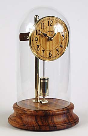
The clock stands twelve inches tall and is housed under a glass dome. The turned base is made of a Brazilian wood called Goncalo Alves. The inside of the base is hollowed out to contain the electronic components and batteries. A polished brass rod supports the dial and the pendulum. The rod has been drilled from the bottom to conceal wires that run up to the electric dial.
The electric dial was made with the stepper motor from a quartz clock movement. The electronic circuit in the base of the clock sends signals to this motor to drive the hands. The face of the clock is made from figured Satinwood with a brass bezel.
The Pendulum
The pendulum rod is 1/8" in diameter and made from a special alloy called "invar". This alloy has the unique property of expanding very little when it gets hot. This is necessary in a mechanical clock, because otherwise the pendulum will get longer, and the clock will slow down, on hot days. The bob is a 2" length of polished brass. The bob is threaded, and can be raised or lowered by turning it on the pendulum rod. This is how you adjust the clock to keep good time. Beneath the bob is a small permanent magnet that forms part of the electromagnetic drive.
The Drive Circuit
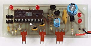
The clock runs on four "AA" batteries which supply power to the pendulum drive circuit and the microprocessor. The drive circuit is based on the design adopted by a Russian named F.M. Fedchenko, who made ultra precision pendulum clocks before quartz clocks made them obsolete. This mechanism consists of two coils of very fine wire under the pendulum, and a permanent magnet on the pendulum that interacts with them. In my clock, the coils are concealed inside the wooden base. One of the two coils is the trigger coil, and generates a voltage whenever the permanent magnet swings near it. The other coil is the drive coil, and it propels the pendulum by attracting the magnet. The trigger coil causes current to flow in the drive coil. This happens on every swing of the pendulum. The rate at which this happens is determined by the natural period of the pendulum, not by the electronics. This type of drive has been used extensively in the past. In addition to Fedchenko, clocks made by Leon Hatot, Bulle, and Brillie used similar permanent magnet drive systems in the 1920s and 30s.
The electronic drive circuit
Voltage Regulation
The electronic circuit in my clock has several features to improve the accuracy over what was possible in the past. One of the problems inherent in early battery clocks was that the voltage decreased as the batteries got old. This tends to make the pendulum swing less wide and changes the rate of the clock. One of the improvements I made in my electronic design was to implement a low power voltage regulator. This is a technology that was not available to makers of battery clocks at the turn of the century.
Rate Adjustment
In antique clocks, to adjust the rate, you must move the bob up or down. For very small changes you might also add or remove tiny weights from a tray on the pendulum rod. Either of these operations is awkward and disturbs the pendulum. I have found that it is possible to fine tune the rate of my clock by making slight changes in the voltage delivered to the drive coil. This takes advantage of the effect that was a major problem for antique clocks. A variable resistor, accessed through a small hole in one side of the wooden base, allows me to alter the voltage to the drive coil and trim the rate of the clock very finely. It's a major improvement over the use of tiny weights on a tray because it can be done without removing the glass dome or disturbing the pendulum whatsoever.
Software Gear Train
The next challenge was to drive the slave dial correctly. This was accomplished with a "software gear train." I measured the period of the pendulum and determined it was near 0.8 seconds per swing. The electric dial advances in whole second increments. In conventional clock terms, I needed a gear train that would convert the 0.8 second swings of the pendulum into one second signals for the dial. I was able to accomplish this by generating 13 pulses for the dial for every 16 swings of the pendulum. This works out to perfect timing if the pendulum is tuned to .8125 seconds per swing, which was easily within the range of my adjustable bob.
The conversion of 16 swings to 13 seconds is accomplished by the microprocessor in the base of the clock. It simply counts the swings of the pendulum and generates signals for the electric dial when they are needed. The microprocessor uses very little electricity and the four "AA" batteries in the clock will last for well over a year.
Performance
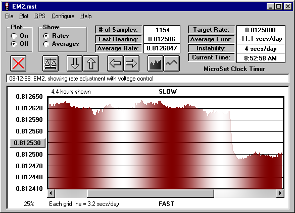
I evaluate the performance of my clocks with the MicroSet clock timer. This is a tool I make and sell for this purpose. The drive circuit in my clock includes a special output for the clock timer which makes it easy to measure the clock without disturbing it.
The clock performs much better than the antique electromechanical clocks it is patterned after. The graph below shows the performance of the clock over several hours. It illustrates an adjustment to the rate via voltage control. The rate was stable at about 12 seconds per day slow. I adjusted the voltage control and brought the rate to very near the correct time of .8125 seconds within 5 minutes. Note that the adjustment happens without disturbance, and this is true for both rate increases and decreases.
Bryan Mumford
Santa Barbara, California
|