
Using the Sherline Motor Controllers with CNC Software
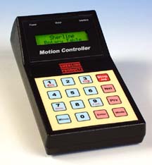
The Sherline motor controllers have been designed to serve as stand-alone controllers for motorizing one axis of a tool. There is a rotary version for the rotary table and a linear version for the feed screws of the mill or lathe. These controllers have built-in commands for moving the tool they're connected to, but they can also be used as "step and direction" motor drivers for CNC programs running on a PC.
If you hold down the "1" key on a Sherline controller when you turn it on, the LCD screen will say "Slave Mode" and the controller will become a simple motor driver. It will accept step and direction signals through the Interface jack at the end of the controller. You will need one Sherline controller and stepper motor for each axis you wish to control, a cable to connect the PC parallel port to the Sherline controllers, and software for your PC that outputs step and directions signals to the parallel port.
Note that the Sherline Rotary Controller and the Sherline Linear Controller work the same in Slave Mode. In other words, if you have one linear controller and the rotary controller, you can use them to drive the X and Y axes of the Sherline mill.
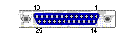
One program you can use to run a Sherline mill is MaxNC DLX. It costs $225. It will interpret industrial standard G-code files and send them to the PC's printer port for the Sherline controllers. You only need to make a cable that connects the printer port to the Sherline interface jacks. The following diagram shows the soldering side of a DB25 male connector that you would use to make this interface cable. Pin one is at the top right corner, pin 25 at lower left.
 Each Sherline controller comes with a "pig-tail" interface cable. This cable plugs into the 8-pin interface jack on the end of the controller. The other end is just cut wires, so you can make any connections you need. To amke this CNC interface cable, we need the STEP and DIRECTION pins. Each Sherline controller comes with a "pig-tail" interface cable. This cable plugs into the 8-pin interface jack on the end of the controller. The other end is just cut wires, so you can make any connections you need. To amke this CNC interface cable, we need the STEP and DIRECTION pins.
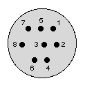 The diagram at right shows the pinout of the Sherline interface connector: The STEP signal is on pin 3. The DIRECTION signal is pin 2. The color coding of the interface cables changes from one batch to another, so you will have to use a continuity checker to find which wires are connected to pins 2 and 3 of each cable. The diagram at right shows the pinout of the Sherline interface connector: The STEP signal is on pin 3. The DIRECTION signal is pin 2. The color coding of the interface cables changes from one batch to another, so you will have to use a continuity checker to find which wires are connected to pins 2 and 3 of each cable.
The MaxNC software supports four axes of motion. The connections you must make for the three primary axes are listed below. You must solder two wires from each interface cables as shown. You must also solder the bare ground wire of each Sherline interface cable to one of the ground pins of the DB25. You can use any pin from 18 to 25 for ground.
|
Sherline signal
|
DB25 pin
|
|
X step
|
2
|
|
X direction
|
3
|
|
Y step
|
4
|
|
Y direction
|
5
|
|
Z step
|
6
|
|
Z direction
|
7
|
Once you have soldered the wires, you can cover the DB25 with a "shell" (a cover) to protect the wires. Plug the DB25 into the PCs printer port. Plug the Sherline interface cables into Sherline controllers. Turn on each Sherline controller with the "1" key held down, so the LCD screen says "Slave Mode". You're now ready to run the Sherline tool with the MaxNC software.
This part is pretty easy. The hard part is writing or generating the G-code files to drive the tool. This can be done by hand, or you can buy software to automatically generate G-code files from drawings.

Voice phone: (805) 687-5116
|